> For the complete documentation index, see [llms.txt](https://docs.holoplot.com/llms.txt). Markdown versions of documentation pages are available by appending `.md` to page URLs; this page is available as [Markdown](https://docs.holoplot.com/holoplot-plan/simulation/tuning.md).
# Tuning
Open the Tuning Panel in the toolbar to see tuning controls for all of the beams in your preset. If you want to tune beams in a specific layer, click on the layer. The contextual menu will appear in the viewport, where the **Tuning Icon** can be clicked.
Tuning Panel
In the Tuning Panel, you can adjust the following parameters:
### Gain
Gain can only be negative and always starts from 0.0 dB. Using the arrow buttons, the Gain is decreased or increased in equal increments. The results will be reflected in the simulation in real-time if the simulation is running.
### Delay
Delay can only be positive, and always starts from 0.0 ms. Using the arrow buttons, the Delay is decreased or increased in equal increments
The Delay Settings featured in the Tuning Panel allow you to adjust the delay of your system without impacting the simulation. This feature can be used to compensate for the time it takes for sound to travel from the array to the audience area. Although the Delay feature does not currently impact the simulation, it will be audible if the configuration from HOLOPLOT Plan is connected to a real-world HOLOPLOT Audio System.
### Input Signal
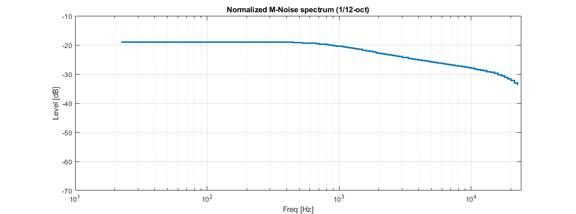
Choose to view how beams perform in the simulation by selecting the AES2, M-Noise or normalized male speech in the input signal drop-down.
* The input signal spectrum of AES2 has a crest factor 4 (12 dB) - band-limited pink noise from 20 Hz to 20 kHz with uncorrelated signals and no interference taken into account.
* M-noise approximates the statistical characteristics of music signals, providing a realistic input for assessing the performance and behavior of audio systems.
M-Noise input signal curve
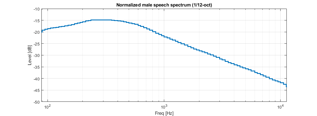
* The IEC male speech spectrum at 1/12-oct intervals is shown below. All levels are normalized to an overall SPL of 0 dB.
Normalized male speech spectrum curve defined by the IEC 60268-16 Ed. 5.0
Both the predicted speech intelligibility and the system power headroom are highly dependent on the spectrum of the speech signal. If the input signal defined when a beam was optimized and is different to the input signal selected for that beam in the simulation, results may look different than expected.
### Mute
Muting a Beam
Use the Mute button to mute any given or multiple beams. Beams can be muted individually. When a beam is muted, the results for that beam will not be calculated in the simulation.
The Mute control only applies to the simulation; beams are not muted when a project is exported to HOLOPLOT Control.
### Solo
Soloing a Beam
Use the Solo button to solo any given or multiple beams. Beams can be soloed individually. When a beam is soloed, only the results for that beam will be calculated in the simulation.
The Solo control only applies to the simulation, and beams will not be soloed when a project is exported to HOLOPLOT Control.
---
# Agent Instructions
This documentation is published with GitBook. GitBook is the documentation platform designed so that both humans and AI agents can read, navigate, and reason over technical content effectively. Learn more at gitbook.com.
## Querying This Documentation
If you need additional information that is not directly available in this page, you can query the documentation dynamically by asking a question.
Perform an HTTP GET request on the current page URL with the `ask` query parameter, and the optional `goal` query parameter:
```
GET https://docs.holoplot.com/holoplot-plan/simulation/tuning.md?ask=&goal=
```
`ask` is the immediate question: it should be specific, self-contained, and written in natural language.
`goal` is optional and describes the broader end goal you are ultimately trying to accomplish on behalf of the user. GitBook uses it to tailor the answer towards what is most useful for that goal.
The response will contain a direct answer to the question and relevant excerpts and sources from the documentation.
Use this mechanism when the answer is not explicitly present in the current page, you need clarification or additional context, or you want to retrieve related documentation sections.