LogoLogo
Hub HomeDownloadsDocumentationReleases
  • Welcome
  • Introduction to HOLOPLOT
    • HOLOPLOT unique capabilities
    • HOLOPLOT technology
    • HOLOPLOT OS
      • Audio signal flow
    • Product family
  • user guides
    • HOLOPLOT system design
      • System design best practices
        • Introduction to sound system design
        • Which HOLOPLOT product is best suited to the application?
        • How do I decide on the position of my arrays?
        • What should be the size and aspect ratio of my arrays?
      • Beam design best practices
        • What are the fundamental principles of designing with beams?
        • How do I set up my coverage zones and what impact does that have on my design?
        • What are the different beam parameters and how do I apply them in my design?
        • How do I apply those beams in real world applications?
    • HOLOPLOT system deployment
      • Integration overview
      • Unboxing
      • Networking overview
      • AES67 Quick start guide
      • Advanced Network Configuration Tips
      • Power
      • Rigging
        • X1 Rigging Components
        • X1 standard rigging side plate attachment guide
        • X1 Standard rigging lifting procedures
        • X1 custom rigging
      • Venue validation
      • System operation & monitoring
      • Pairing the arrays & routing audio
      • Align and tune beams
      • Measurement and system optimization
    • Troubleshooting
  • HOLOPLOT Plan
    • Getting started
      • Recommended specifications
      • Installing HOLOPLOT Plan
      • Additional 3rd party tools
      • Navigating the interface
    • Onboarding videos
    • Importing 3D assets from SketchUp
      • Setting up the SketchUp toolkit
      • Installing the Khronos glTF Exporter for SketchUp
      • Defining zone types in SketchUp
      • Importing assets from SketchUp
    • Working with Matrix Arrays
      • Creating arrays
      • Moving arrays
    • Working with zones
      • Defining zone types
      • Drawing zones
      • Moving zones
    • Working with presets
      • Creating a preset
      • Working with preset layers
      • Working with environmental conditions
    • Working with beams
      • Creating a Parametric Beam
        • Adjusting Parametric Beam parameters
      • Creating a Virtual Source
        • Adjusting Virtual Source parameters
      • Creating a Coverage Beam
        • Assigning zones to a Coverage Beam
        • Adjusting Coverage Beam parameters
        • Optimizing a Coverage Beam
        • Working with beam variants (advanced)
      • Creating an LF Coverage Beam
        • Creating crossovers
      • Routing Beams
    • Simulation
      • Simulation controls
      • Tuning
      • Probe Mode
      • Simulating with S21 arrays
    • Saving & exporting
      • Exporting to AFMG EASE
  • HOLOPLOT Control
    • Getting started
      • Accessing HOLOPLOT Control
      • Navigating the interface
    • Configuring the system
      • Setting up system essentials
      • Managing a project
      • Pairing Modules
      • Network Settings - RAVENNA only
      • Stream Management - RAVENNA only
      • Setting up Analog mode on X2 Modules
    • Operating the system
      • Getting an overview of the active project
      • Routing streams to audio inputs
      • Switching presets and environmental conditions
      • Applying actions to the system
      • Tuning beams
      • Monitoring level meters
    • Maintaining the system
      • Monitoring device health
      • Module driver test
      • Module and Controller events
      • Module and Controllers Issues List
  • HOLOPLOT API
    • Getting started
    • Documentation
      • Arrays and modules
      • Beams and presets
      • Device health
      • Controllers
      • System operation
      • Spaces
    • Examples
      • Changing a preset
      • Adjusting the system's gain
Powered by GitBook
On this page
  • Overview of Coverage Beam parameters
  • General beam parameters
  • Air absorption compensation
  • SPL Drop
  • Beam variant-specific parameters
  • Target response
  • Phase Response
  • Input Signal

Was this helpful?

Export as PDF
  1. HOLOPLOT Plan
  2. Working with beams
  3. Creating a Coverage Beam

Adjusting Coverage Beam parameters

PreviousAssigning zones to a Coverage BeamNextOptimizing a Coverage Beam

Last updated 10 months ago

Was this helpful?

LogoLogo

HOLOPLOT

  • HOLOPLOT Website
  • Contact
  • Imprint
  • Privacy Policy

© 2024 HOLOPLOT GmbH. All rights reserved.

Overview of Coverage Beam parameters

You can adjust the following parameters in the Coverage Beam Properties Panel on the right. Some parameters are general to the beam, meaning they cannot easily be changed once the beam is optimized. Other parameters are more flexible and can be changed or adjusted by adding a new variant of the beam.

To find out how to use the beam parameters most effectively in your system design, head to What are the different beam parameters and how do I apply them in my design?

General beam parameters

These parameters appear at the top of the coverage beam panel and cannot be easily changed. They will persist in every instance of a beam.

Air absorption compensation

The Air Absorption Compensation slider allows the sound pressure level to be maintained over a longer distance by compensating for the signal loss due to air absorption.

In long-throw applications, high-frequency propagation is strongly affected by air absorption. This effect can be counterbalanced by HOLOPLOT’s air absorption compensation tool. This tool is not a simple signal EQ, but rather a 3D spatial EQ that compensates HF air absorption effectively in a direction and distance-dependent way. To avoid excessive compensation levels at high frequencies, the maximum compensation can be set to realize an optimum trade-off between spectral uniformity and max. obtainable SPL. For very high frequencies and/or receivers at very large distances for which the level can never be completely restored, the compensation level drops to guarantee driver integrity and system headroom.

SPL Drop

The SPL drop over distance parameter in Coverage Beam optimization allows you to determine the decrease of sound pressure level (SPL) along the audience area. Use the SPL Drop slider to adjust the desired level drop across the audience from 0 to 6 dB per distance doubling. This parameter is especially useful in setups with small arrays at a low mounting height, allowing some level drop over distance to improve spectral uniformity.

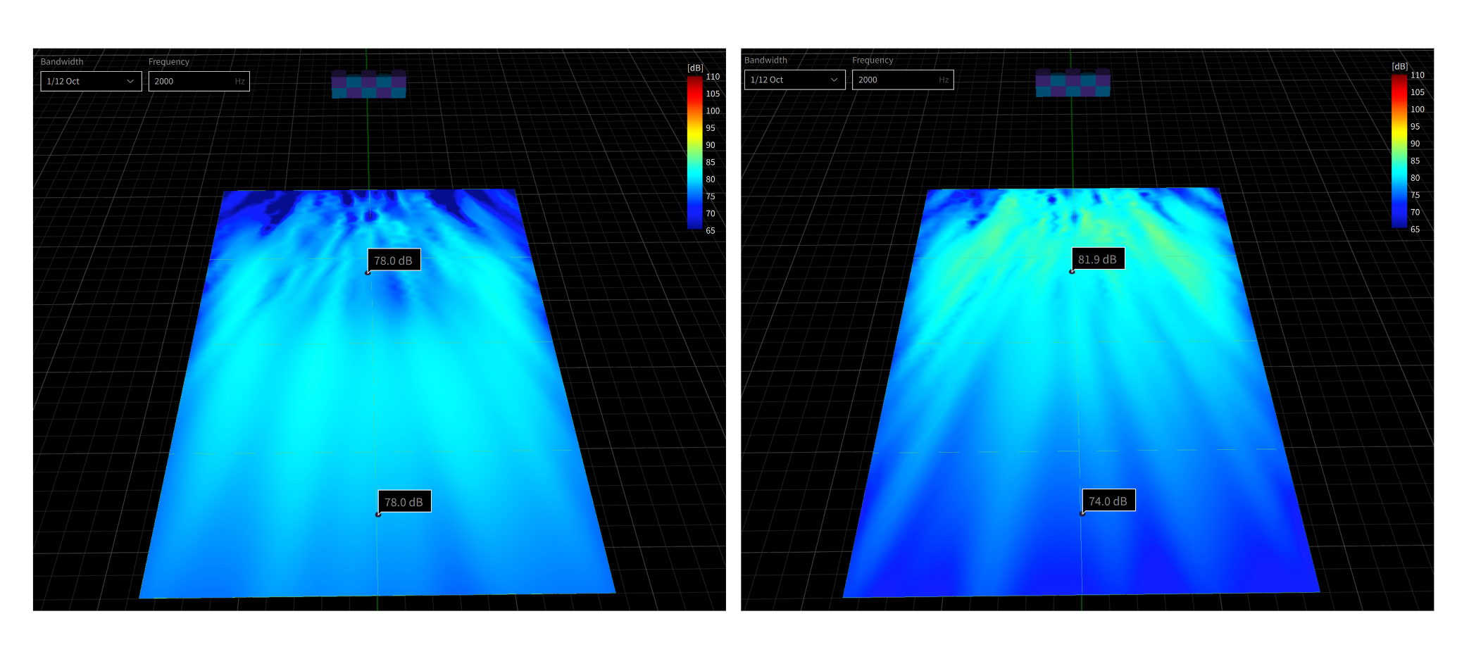
Left - SPL Drop over Distance: 0 dB per distance doubling / Right - SPL Drop over Distance: 6 dB per distance doubling

Beam variant-specific parameters

Below the general parameters, you'll find the Coverage Beam parameters which are specific to the beam variant. Only one version of a beam variant can be used in a preset layer. Find out more in the Working with Beam Variants section.

Working with beam variants (advanced)

Edit the following parameters and click Optimize to create a beam.

Target response

Chooses a predefined frequency response for the optimization. By specifying the target frequency response curve for the optimization, you can effectively achieve the desired sound at the selected audience zone, saving time (and headroom) during the tuning phase. Defining the system frequency response using the target response will automatically adjust the DSP chain (up or down) to reach 0 dB headroom in any passbands. Alternatively, using a parametric EQ on the beam might overdrive the system, causing a lack of headroom, or underuse it, resulting in excess headroom. Consequently, using the target response makes the most out of the available headroom, allowing for a more efficient tuning process. You can select the target response from a list of predefined curves:

  • Flat

  • Low-shelf +7 dB

  • Low-shelf +6 dB

  • Low-shelf +3 dB

  • High-shelf +9 dB

  • High-shelf +6 dB

  • High-shelf +3 dB

Phase Response

The Phase Response feature in HOLOPLOT Plan allows you to choose the phase behavior of the Coverage Beam, effectively adjusting the group delay of the array's different passbands.

There are four different phase response options available:

Phase Response
Information

Linear Phase

Constant group delay across the entire frequency range (>30Hz). Long latency (51 ms)

Mixed Phase

Constant group delay above ~60Hz, increasing towards low frequencies. Medium latency (31.2 ms)

Near-Minimum Phase

Constant group delay above ~100Hz, increasing towards low frequencies. Medium/Low latency (9.3 ms)

Minimum Phase

Constant group delay above ~200Hz, increasing towards low frequencies. Low latency (4.7 ms)

Input Signal

Defines an input signal - this should correspond to the type of content that will be played from the system. The input signal selected will have an effect on the maximum amount of headroom available

The input signal can be defined for beams during optimization and is important for maximizing the amount of headroom available in the array. There are three different input signals to choose from, dependent on the type of content you intend to play through your beam.

AES2 (pink noise)

The AES2 input signal is a standardized audio test signal defined by the Audio Engineering Society (AES). It is commonly used for evaluating the performance and calibration of audio systems. The AES2 signal, characterized by a flat frequency response, provides a consistent and reliable reference for testing purposes, and is the default input signal that beams for X1 arrays are optimized with.

Male Speech

The long-term average speech spectrum of male talkers is defined by the IEC 60268-16 Ed. 5.0. This standard describes methods for the objective rating of speech intelligibility by the Speech Transmission Index (STI). The latest edition 5 contains an updated version of the male speech spectrum. The female spectrum has been removed. Both the predicted speech intelligibility and the system power headroom are highly dependent on the spectrum of the speech signal. The IEC male speech spectrum at 1/12-oct intervals is shown below. All levels are normalized to an overall SPL of 0 dB.

M-Noise

M-noise refers to a specialized noise signal used in audio measurements and simulations. It approximates the statistical characteristics of music signals, providing a realistic input for assessing the performance and behavior of audio systems. M-noise captures the broad frequency range, transient dynamics, and tonal variations found in music, enabling accurate evaluations of audio equipment's fidelity and capabilities.

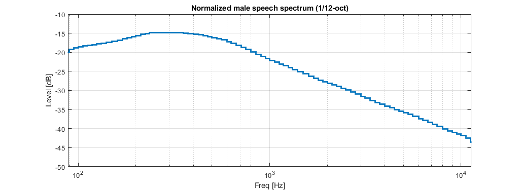
Normalized male speech spectrum curve defined by the IEC 60268-16 Ed. 5.0.
M-Noise input signal curve